Switch Stands
One of my goals when building Southern Railway 1966 was to install operating switch stands. I purchased four different manufactures stands before settling on Rapido’s RailCrew Switch Stand Kit. They now produce a switch motor and stand in one installation. I started building my layout before that was available.
Installing a RailCrew Switch Stand
The method I use to add switch stands to Peco USA Line switches is far from perfect but it gets close enough and has proven very effective. It can involve some trial and error but with repetition it’s possible to get good, repeatable results.
The Look
Switch stands, particualry operating switch stands, offer a neat detail for an operating layout. They serve as an added spotting feature to indicate the direction of a switch from a distance.
As always, try to locate photographs or prototype information of switch stands appropriate to your railroad. That can be difficult for right-of-way details. In this case I was able to gain information from a copy of the Southern Railway Operating Rules 1956 I found online.
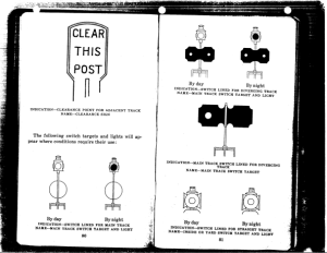
Excerpt from Southern Railway Operating Rules 1956
For this project though I’ve opted to use a set of indicators that do not match the prototype as that’s what I had at hand.
Model Switch Stands
I tried three different switch stands before settling on Rapido’s RailCrew Switch Stand Kit:
- I started with Caboose Industries – over scale,
- Rix Products – didn’t appeal,
- Details West – not able to be easily automated.
The Rapido switch stand has fidelity and the attention to detail I like.
Installation
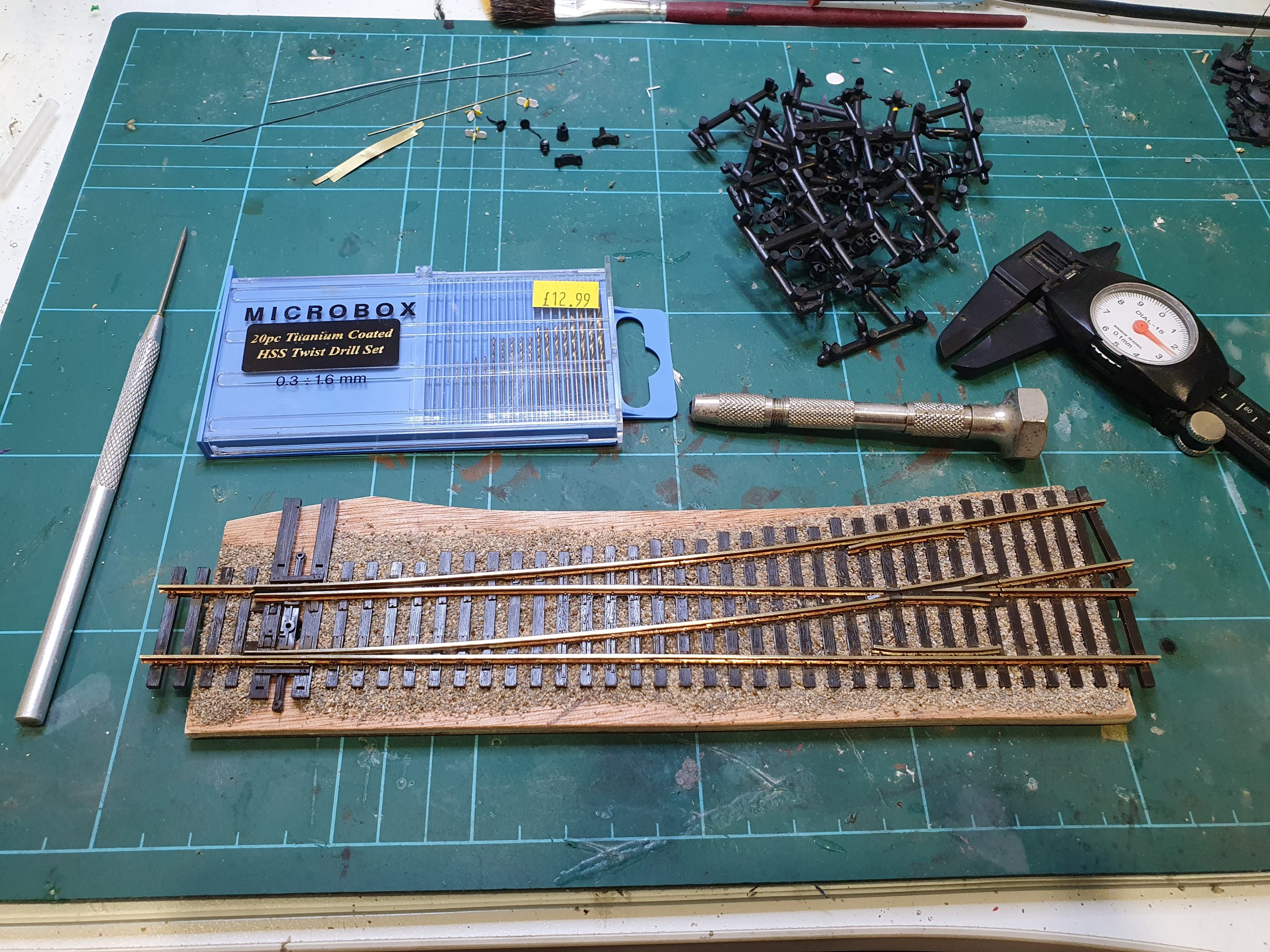
I use Peco USA Line switches. These have extended ties to mount a switch stand. Iadvise looking at the photographs in the gallery as well as my process below:
- Drill two 0.6mm holes in the ties sufficiently far from the track to accommodate lateral movement in the linking rod to mount the Rapido switch stand base
- Mount the Switch Stand base and drill a 0.6mm hole through into the baseboard to act as a pivot-point for the mast-arm
- Create a pivot lever from brass shim with one 0.6mm hole and one 0.8 mm hole, 0.9 to 1.0mm apart. The 0.6mm hole is for the mast arm, the other for the linking rod
- Solder the pivot lever to the mast arm, 3.0mm from the end. I’ve found ordinary lead-tin solder to be adequate. CA glue is also an option
- Remove excess shim from the pivot lever to avoid it catching in the ties
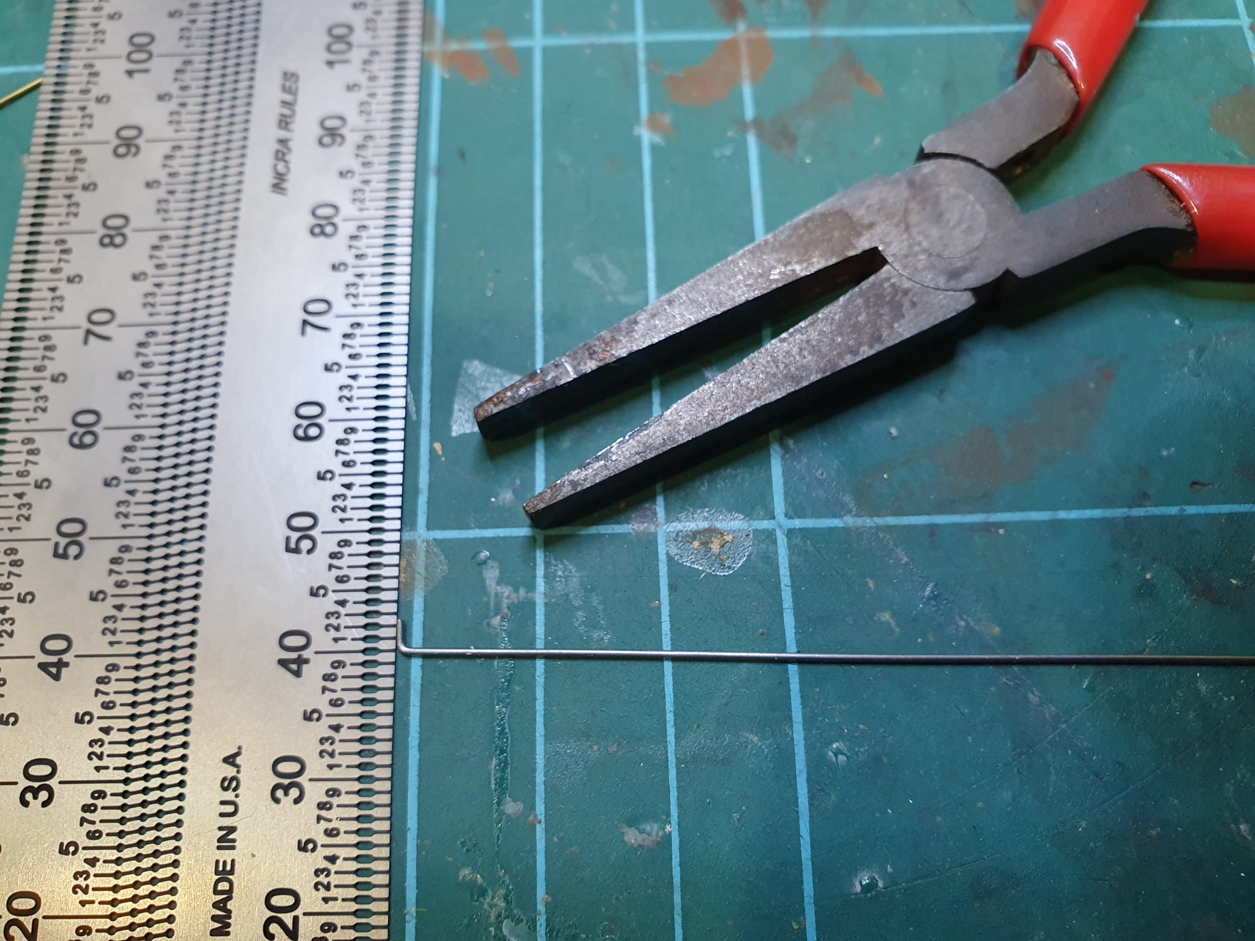
- Using 0.5mm steel spring wire, bend at 90 degrees a 2.0mm “Hook” to connect to the switch tie bar
- Now the tricky part that will almost certainly involve trial-and-error. Bend the opposite end of the linking rod to form a hook, folding the wire 180 degrees, with about a 5.0mm lap, but with enough gap to insert in the o.8mm hole in the pivot lever. The length of the linking rod will take a few attempts to narrow down. The mast arm should rotate only 90 degrees. I found I can generally achieve 90-110 degrees which I’m usually happy enough to live with
- Assemble the linking rod, switch stand and mast arm. Add a small drop of medium CA glue where the link rod joins to the Peco switch tie bar
- Cut the mast arm to length and add the appropriate indicator for your railroad.
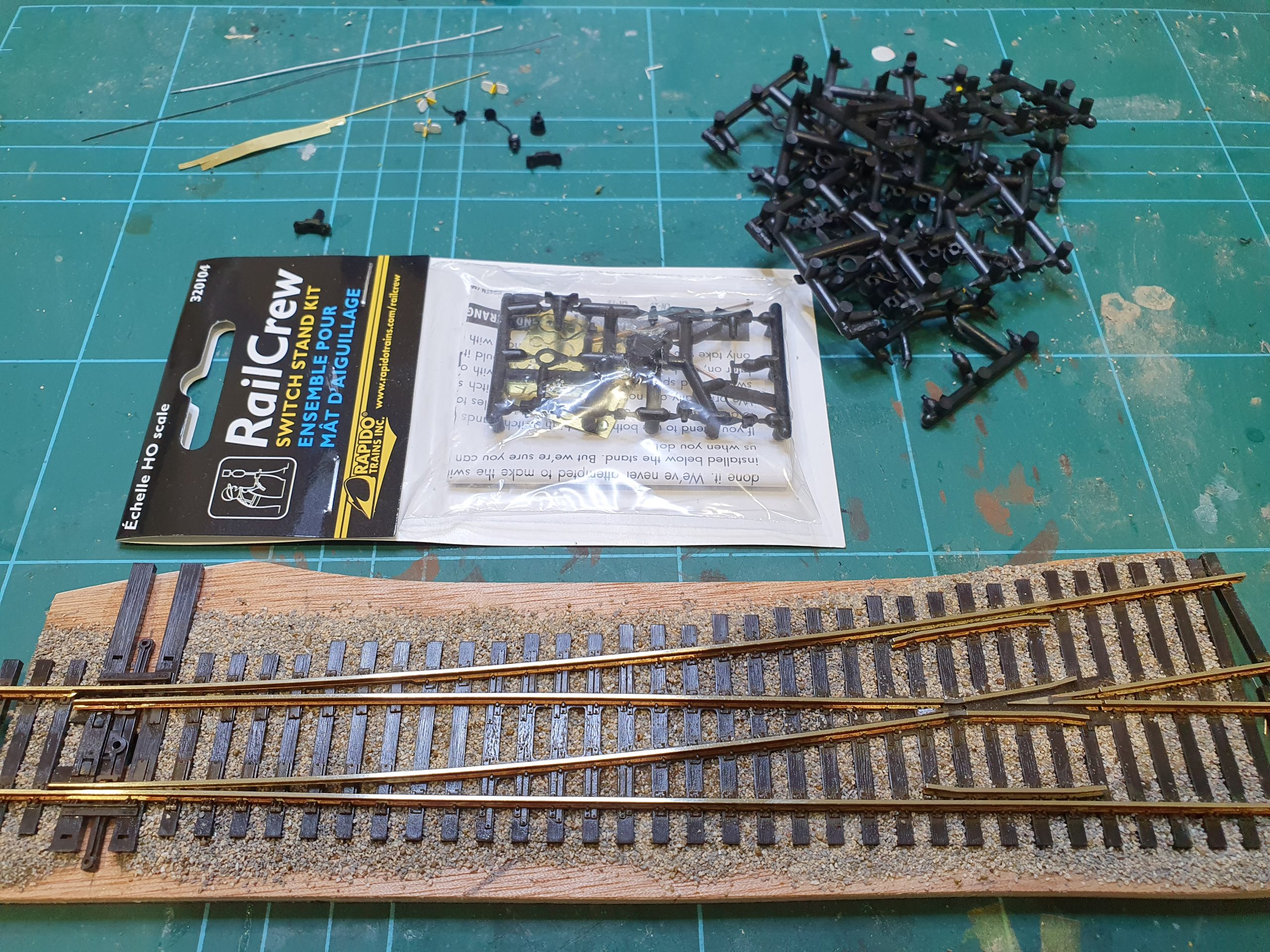
Switch Stand
Spare Sprue Parts, and original unopened RailCrew Pack

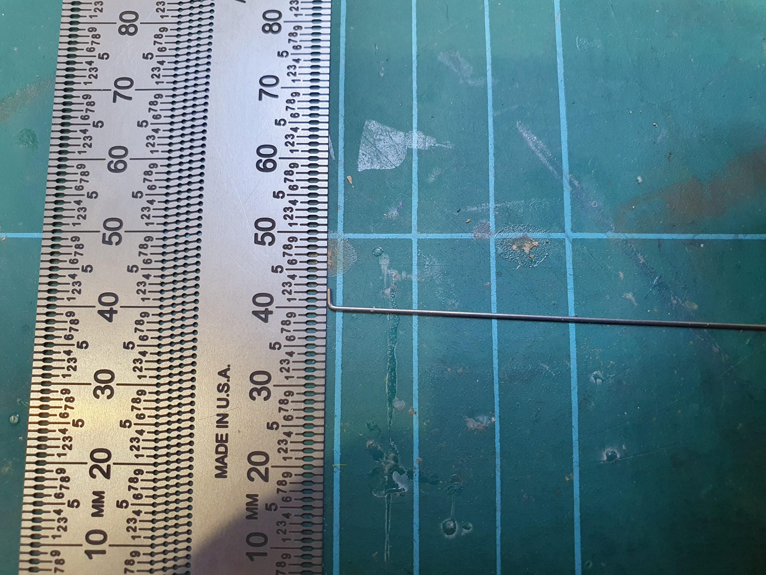
Switch Stand
Connecting rod prior to folding right piece 180 degrees

Switch Stand
Marking off connecting rod length
Switch Stand
connecting rod forming
Switch Stand
Connecting rod forming

Switch Stand
Pivot soldered to mast – prior to cleaning up

Switch Stand
Lever arm (3 mm down shaft) on mast arm ready for soldering

Switch Stand
Lever arm shim with two holes drilled 1mm apart

Switch Stand
Lever arm shim

Switch Stand
Lever Arm Shim

Switch Stand
Drilled hole in switch lever
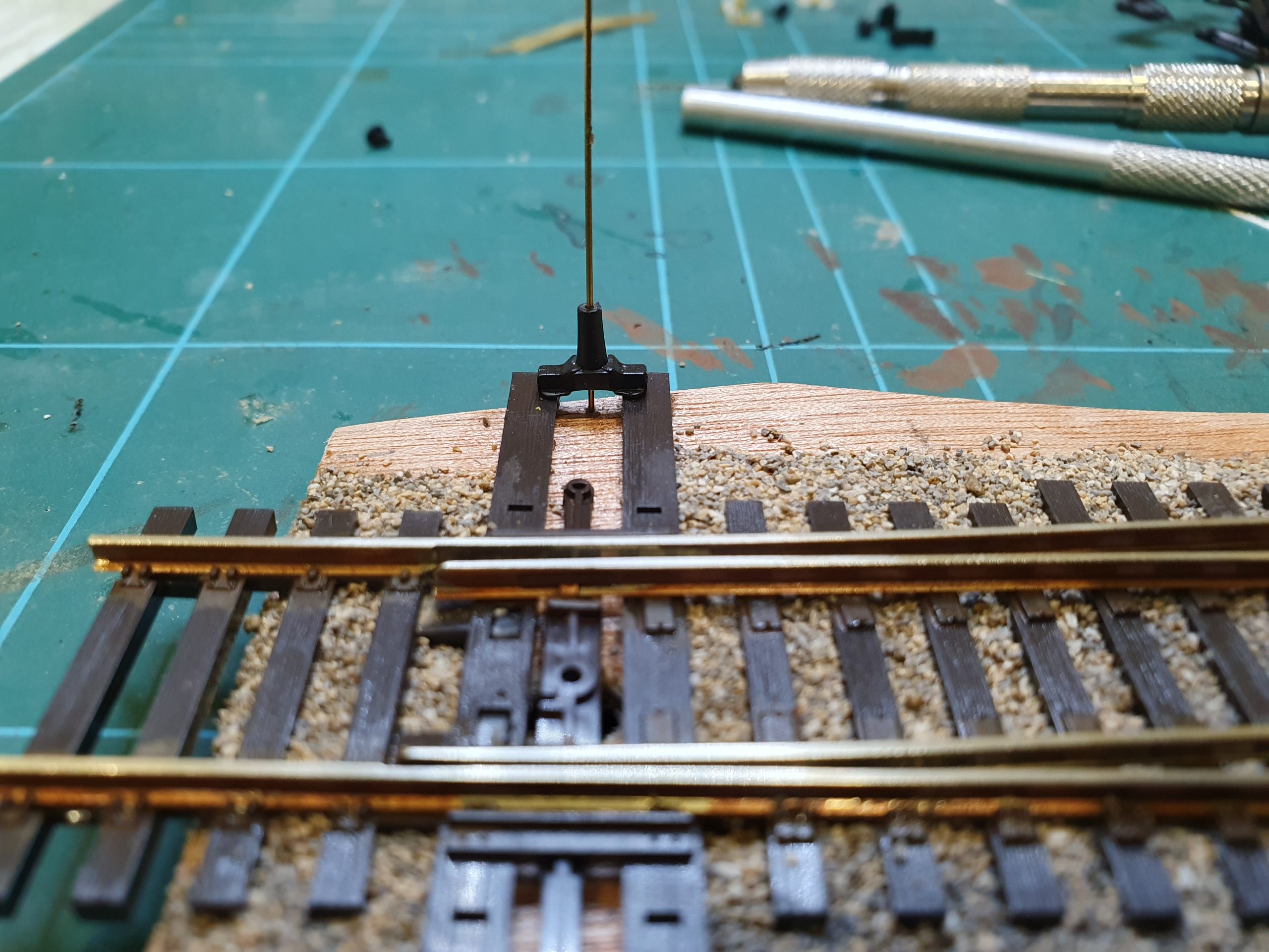
Switch Stand
Switch mast through switch stand and in to pivot hole

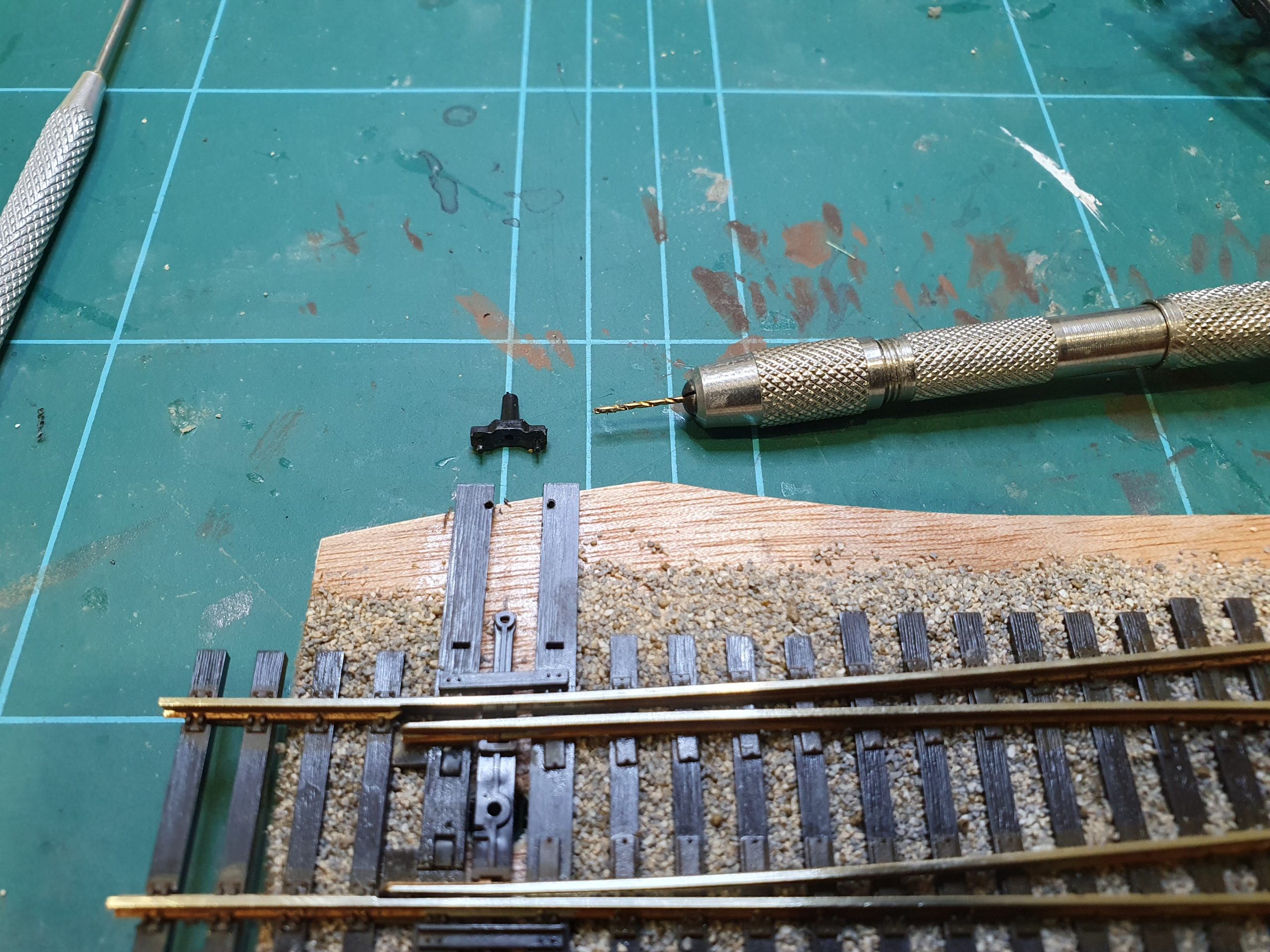
Switch Stand
Drilling pivot hole in base
Switch Stand
Holes drilled for switch stand
Switch Stand
Holes drilled for Switch Stand
0 Comments